1. Removing the top cover

Turn the ring to X and loosen the countersunk grub screw (left do not unscrew!).
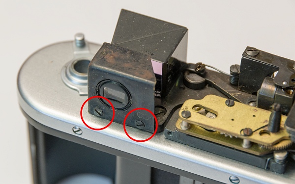
Remove the two screws holding the cover and the cover screw of the horizontal adjustment screw (bottom and bottom left).


Unlike its predecessor, the Zorki 4K has a quick-release lever. It is very practical, but this also means that there is a spring inside that automatically returns the lever to its original position.
If we simply remove the quick-release lever, the spring would relax and we would have to laboriously wind it up again. This must be prevented.

Remove the screw and take out the film counter disc and the spring washer (left and bottom left).
Now remove the disc with the two holes. Caution: left-hand thread! The disc may be very tight, so a spanner is usually required. The disc also holds the film take-up spool in place (bottom).


Film take-up spool and disc (left).
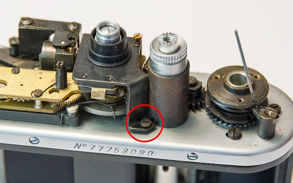
Now comes the trick to prevent the spring from releasing: wind the camera until the small hole (arrow!) is to the right behind the upper housing screw. Then insert a needle into the hole and release the tension lever. The tension lever should now remain in the position shown. Now the three screws can be removed. Then carefully remove the disc with the three holes and the tension lever. Be careful not to let the needle fall out! (bottom left)
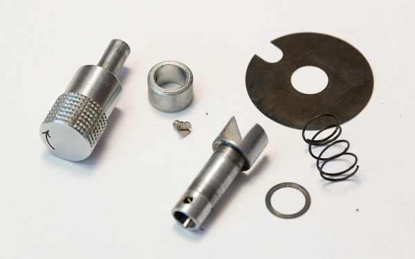
Parts of the tension lever (bottom).


Finally, this screw must be removed. Then the cover can be taken off. Watch out for the needle! (left)
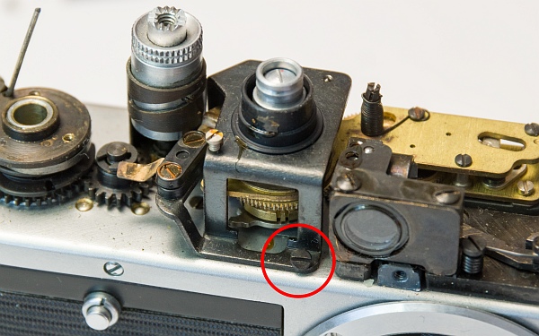
Now we unscrew the two screws inside the cover (bottom left). They hold the disc with the shutter speeds and the ring for setting the flash delay (bottom).


2. Other parts

First, here is a picture showing how the needle blocks the spring under the tension lever (left).
Now we remove the rewind crank (as already shown in other instructions) and obtain these parts (bottom left).
To clean the rangefinder, remove the cover with the eyepiece in front of the dioptre adjustment lens (bottom).
These two screws (at the very bottom) hold the flash delay unit in place.
3. Adjusting the rangefinder

This lens is used to adjust the vertical offset. Turning it to the left moves the rangefinder spot upwards, turning it to the right moves it downwards.
The lens is fixed with shellac. Using a small brush, a little pure alcohol or isopropanol is dripped into the gap. After one to two minutes, the lens can then be turned with a spanner. Once the alcohol has evaporated, it will be firmly in place again.
The horizontal offset is adjusted using the small screw on the right-hand side of the circle.
Originally, I only wanted to adjust the vertical offset, so I didn't dismantle the body. But then I decided to take the camera apart further to service it completely.
4. Remove the housing

First, remove the self-timer lever. Caution: left-hand thread!
This part can be quite tight. If you don't have a small spanner, remove it using either a rubber glove or an eraser (bottom left).
The parts of the self-timer lever. The lever, the connector between the lever and the self-timer, screw and seal (bottom).


After removing the lower cover of the shutter (2 screws), we see the tension screws for the springs of the first and second curtains. These have apparently never been readjusted on this camera; the locking lacquer is still intact (left).
Now remove the screw ring for the lenses and the housing screws. Pay attention to the wax paper discs for adjusting the flange focal distance. When reinstalling, these must be positioned exactly as before.
One of the housing screws is shorter than the others. It belongs in this position (arrows).


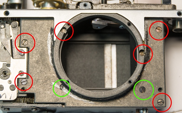
After removing the casing (the casing is glued with shellac, which can be more or less difficult), we remove the cover plate of the closure. A total of 8 screws hold it in place. 2 of them (green) are shorter (left).
The plate, the screws and the two covers of the shutter drums (bottom left).
The two large gears need to be cleaned and re-lubricated (bottom). I clean them with a toothbrush and lighter fluid and then oil them with a little resin-free sewing machine oil.
To do this, I put the tension lever back on provisionally and remove the needle so that I can tension and release the shutter.
These gears should also be oiled a little (bottom left).
The clean lenses of the rangefinder (bottom).


5. Overview

All parts laid out clearly after cleaning.
6. Assembly

After putting the cover back on, reassemble the tension lever. Replace the lever and disc with the needle inserted. One of the screws can now be screwed in halfway with a little fiddling. Then the needle can be pulled out and all 3 screws can be inserted (left).
The pawl spring must be moved to this position (arrow) before the film take-up spool is attached with the disc with the two holes (remember the left-hand thread!) (bottom left).
Then apply a little grease and screw the spring disc back on together with the frame counter (bottom).
The housing must now be reattached with the 5 screws.


Replace the wax paper adjustment discs in the same way you removed them. It can be annoying if they consist of lots of small pieces... Then screw the lens mount back on. The dot on the inside must point downwards so that the infinity mark on the lens is at the top (left).
Then reattach the self-timer. First, put on the small rubber seal, then insert the connector between the lever and the self-timer (it only fits in one position), then put on the lever and secure everything with the screw. Again, pay attention to the left-hand thread!
Now we put the base plate back on. The longer of the two spacers goes on the right (at the very bottom).


7. Lens care

Servicing the lens is described here.
8. Result

Ét voila! A camera just like the ones in the shop!

